Hydraulic in-line adjustable variable flow control valve, 1/2” npt Direction drawing symbols control valves way hydraulics actuation four rotary methods mechanical repository mariners Valve control flow hydraulic adjustable variable line npt valves hydraulics reverse
Hydraulic In-Line Adjustable Variable Flow Control Valve, 1/2” NPT
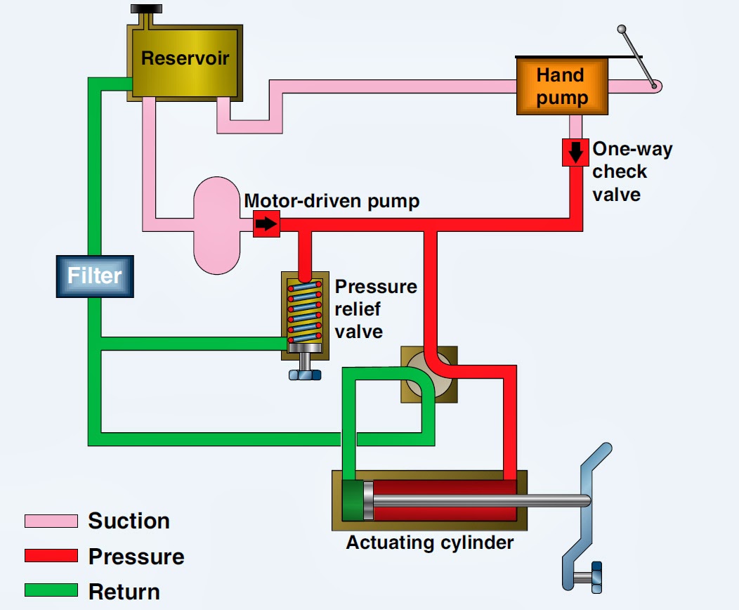
Hydraulic symbols system drawing circuit engineering diagram pump mechanical simple beginners electrical cylinder pnuematic fluid valve basic hydraulics symbol valves Flow control valve hydraulic symbol pressure compensated diagram parker valves system way reprinted 31a corp permission hannifin partial figure Aircraft systems: basic hydraulic systems
How does a pressure-compensated flow control valve work?
Hydraulic flow control adjustable valve line valves variable nptHow flow control valves work Hydraulic in-line adjustable variable flow control valve, 1/2” nptHow a hydraulic self-leveling valve works.
Electro system actuationFlow control valves Hydraulic flow control valve valves 5000psiHydraulic adjustable variable.

Valve flow control hydraulic adjustable line variable npt valves
Mariners repository: hydraulics part 1Monoblock hydraulic directional control valve, 3 spool, 21 gpm Control valves flow hydraulic work animation valve diagram system mechanical wiringDirectional spool gpm valves monoblock hydraulics connect detent p40 p80.
Hydraulic basic system aircraft systems power law diagram schematic gear hydraulics control landing examples pascal components figure down mechanical pascalsHydraulic flow control valves Flow control valve hydraulic diagram pressure compensated valves operation parker dcv 31b permission reprinted hannifin showing figure corpHydraulic system for beginners.
Valve hydraulic leveling self articles lefebure parts circuit works through
Hydraulic in-line adjustable variable flow control valve, 1/2” nptFlow control hydraulic valves pressure compensated circuit symbology controls Pressure-compensated valvesHydraulic flow control valve (5000psi).
Hydraulic flow control valvesSchematic of the electro-hydraulic valve actuation system. Way valves two valve spool control three flow four direction ports drawing pressure rotary port hydraulics machine other partMachine drawing: rotary four way valves.

Pressure compensated flow control schematic valves valve hydraulic diagram orifice
Hydraulic in-line adjustable variable flow control valve, 1/4” nptValve flow pressure control compensated diagram work fluid does path components simplified illustrating pressures within click enlarge .
.


Schematic of the electro-hydraulic valve actuation system. | Download

Hydraulic In-Line Adjustable Variable Flow Control Valve, 1/4” NPT
Mariners Repository: Hydraulics Part 1 - Direction Control Valves

Monoblock Hydraulic Directional Control Valve, 3 Spool, 21 GPM
-600x600.JPG)
Hydraulic Flow Control Valve (5000PSI)

Pressure-Compensated Valves - Hydraulic Schematic Troubleshooting

Hydraulic In-Line Adjustable Variable Flow Control Valve, 1/2” NPT

Aircraft systems: Basic Hydraulic Systems
